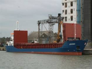
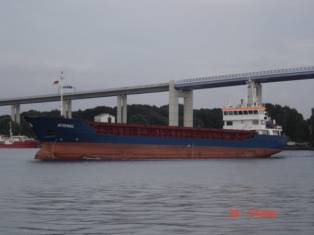
GENERAL PROVISIONS M/V THUNDER
Main data MV Thunder
status:
In service
type: Mini Bulkcarriers (2001-3000 GT)
call sign: V2LB
imo no: 9 199
139
builders: Schiffswerft Hugo Peters,Wewelsfleth Peters&Co. GmbH
yard no: 2950
delivery: 2007-07-01
owner
agent:
port of registry: St. John's
flag: Antigua & Barbuda
class. hull: GL 100 A5 E G DG DBC
class. mach.: MC E AUT
Overall
dimensions
tonnage
GT [t]: 2461
tonnage NT [t]: 1369
deadweight [t]: 3700
lenght o.a. [m]: 87.84
lenght b.p. [m]: 81
breadth [m]: 12.8
depth to maindeck [m]: 7.1
depth to tweendeck [m]: 4.55
draught (summer) [m]: 5.51
|
|
|
Propulsion, deck
outfit
main
engine: 1 DEUTZ diesel, type SBA8 M
528, 441 kW at 620 rpm; 1 reserve/reduction gear; 1 propeller
auxiliary engines: 1Deutz
Diesel BA 6M 816oLLk, 184 kW with NKT
220-4 generator 210 kVA, 380/220 V, 50 Hz;
1 Deutz Diesel F5L413 FR
68 kW with NKT generator 75 kVA, 380/220 V, 50 Hz;
shaft generator: Piller NKT 60-4 generator 57 kVA, 380/220 V, 50 Hz;
equipment:
bow thruster 132 kW, 2 radars, gyro compass, autopilot, GPS, DGPS, echo
sounder, rate of turn indicator, SATCOM, VHF-unit, GMDSS fitted, electr. hydr.
steering gear hatch/hold 1 [m]: 56.55 x 10.20
Operating speed - speed [kt]: 11.3
ENGINE ACCOMODATION
Main
Engine DEUTZ SBa 8M 528 is situated on aft side the vessel inside engine room:
|
|
|
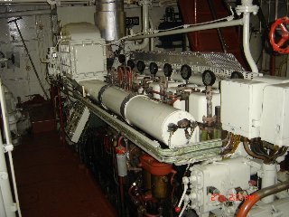
Engine
room is composition of the following rooms:
-
separated
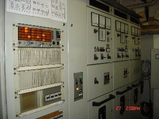
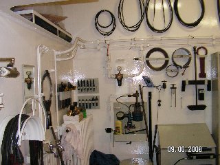
Engine Control Room with Main switchboard and workshop:
|
|
|
-
steering
gear and bowthruster room
|
|
|
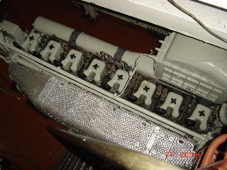
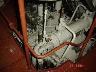
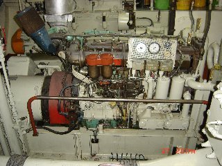
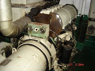
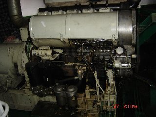
![]() MAIN ENGINE DEUTZ SBA 8M 528
MAIN ENGINE DEUTZ SBA 8M 528
1. Technical description
The
propulsion plant serves for ship's propulsion.
The
main parts are:
- The main engine, type DEUTZ MWM - stand type, 8 cylinders,
water-cooled, non-reversal, with direct fuel injection, overcharged by cooled
air, with air-starter and electric control. Engine type SBA8
M 528, 441 kW at 620 rpm.
- The diesel engine is
connected with reducing gearbox REINTJES WAV 1830 by elastic connector VULKAN
type EZ 165 BR 123. Line shafting with fixed-pitch propeller is driven through
a fast collar coupling on the propeller shaft of the gearbox. The engine is
equipped by a hydraulic regulator with revolution regulation and stopping unit.
-Reducing gearbox REINTJES WAV
1830 gear ration i=2,542:1, with vertical offset of the engine and propeller
shaft,
-Line shafting with fixed-pitch
propeller diameter of 2000mm for the ice class E.
-Shaft seals are made by Blohm+Voss company, type
SIMPLEX-SEAL HDW 240.
-
Pneumatic remote engine revolutions control system enables control from the
panel of ME, Engine Control Room and in the wheelhouse.
2. Basic maintenance:
1 Check oil level - daily
2 Check cooling water level in
expansion tk - daily
3 Check engine exterior for loss of
oil, fuel and coolant - daily
4 Check operating pressures, temperatures and all
others ME working parameters, visual checks and running noises - daily with engine running
5 Draining water from air receivers
- daily
6 Check level in leak oil tank and
empty it into day tank – daily, acc. need
7 Drain condense. water from pneumatic
control system - daily
8 Drain water before main starting
valve - before starting
9 Checking the cooling water quality - weekly
10 Collecting sample of lub oil ME
system - monthly
11 Sending the lub oil sample for
analysis - monthly
12 Collecting sample of fuel (keep OB 1
year) - while bunkering
13 Inspecting valve
rotator - 250 hrs
14 Servicing centrifuge lub. oil filters - 250 hrs
15 Attached LO pump of ME check for
leakages, unusual noises and overheating - daily with engine running
16 Stand-by LO pump of ME check for
leakages, unusual noises and overheating - after start
17 Stand-by LO pump of ME bearing
regreassing - 500 hrs
18 Stand-by fuel pump of ME check for
leakages, unusual noises and overheating - after start
19 Stand-by fuel pump of ME bearing
regreassing - 500 hrs
20 Cleaning fuel oil duplex filter - 500 h or
if need
21 Oil change in turbocharger - 500 h or
if need
22 LO
and microfilter change in fuel oil pump-1000 h
23 Cleaning or changing the filter mat
of turbocharger - 100 h
24 Cleaning of rotary filter - 250 h
25 Check engine alarms, emergency stop
devices - every 500 h
26 Checking injection nozzles - 3000 h
27 Checking valve clearance - 1000 h
28 Cleaning manoeuvring air
starting valve - every 3. month or if need
29 Governor oil change - 1000 h
30 Changing
CJC filter - if need
31 T/C visual inspection/check for abnormal noise - daily
32 T/C compressor washing during operation (with clean
water) - daily
33 T/C cleaning/renewal of air filter mat at silencer - every 100 hrs
34 T/C check fastening bolts at the feet, tighten all housing bolts and
piping joints every - 1000 hrs
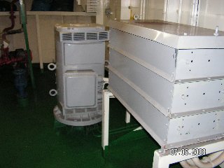
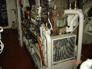
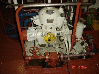
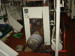
![]() THE DIESEL PLANTS
THE DIESEL PLANTS
1.
Brief technical description
The
auxiliary diesel plants and shaft generator serves for the supply of electric
energy to all mechanisms and equipment which ensure the ship's normal
operation.
Main
parts:
-1 pc of diesel plant 210 kVA, consisting of engine
type Deutz Diesel BA 6M 816oLLk, 184 kW with
NKT 220-4 generator
|
|
|
-1 pc of Piller shaft generator plant 57 kVA,
consisting of gear type PIV type BRHN 53, n=750/320 rpm 52 kW with NKT 60-4 generator
|
|
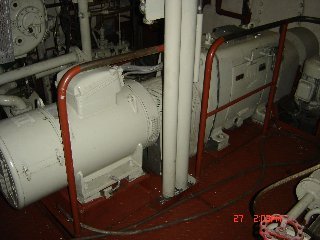
-1 pc of harbour diesel plant 75 kVA, DEUTZ
KHD F5L413 FR 68
kW with generator NKT 90-4 generator
|
|
|
The
engine of the auxiliary diesel BA 6M 816oLLk, 184 kW plant is turbocharged
plant, equipped with pneumatic starter, water cooling system with oil cooler,
mechanic regulator of revolutions and with smooth electric remote regulator of
revolutions. The shaft generator plant serves the electric power supply during
sea passage and can work in paraller mode with diesel engines fro short time
and only for switch over.
The engine of the harbour diesel plant DEUTZ
KHD F5L413 FR 68
kW is equipped with pneumatic starter, air cooling system, mechanic regulator
with mechanic smooth regulation of revolutions. A separate hand air compressor
serves for emergency starting.
2. Basic maintenance for diesels
1 Check oil level - daily -
engine stopped
2 Check cooling water level in
expansion tk - daily
3 Check engine exterior for loss of
oil, fuel and coolant - daily
4 Check operating pressures, temperatures and all
others working parameters of the engine, visual checks and running noises - daily - with engine running
5 Check fuel lines for leaks every - 200 hrs
6 Fuel hi-pressure pipe leak alarm
device function test every - 500 hrs
7 Check engine alarms,
emergency stop devices - every 500 hrs
8 Check coolant
preheating, function, settings every -
200 hrs
9 Check the cooling water quality - weekly
10 Check V-belts tension, re-tightening if
necessary - every 200 hrs
11 Check water hose clamps, pipe
connections and bolds for security, re-tightening if necessary - every 200
hrs
12 Cleaning of fuel pre-filter - every 200
hrs
13 Change engine oil - every
250 hrs
14 Change oil filter cartridges - every 500
hrs
15 Service the air cleaner - every 200
hrs
16 Check valve clearance, setting if
necessary - every 1000 hrs
17 Change of fuel filter - every 500
hrs
18 Change of fuel filter - every 500
hrs
19 Check injectors, replacing if
necessary - every 3000 hrs
2a.
Basic maintenance for shaft generator
1 Check oil level - daily -
engine stopped
2 Check operating working
parameters of the shaft, visual checks and running noises - daily - with engine running
3 Change oil- every
2000 h
4 Cleaning oil filter upper- every
1000 h
5 Cleaning oil filter lower- every
2000 h
6 Greasing bearings – not too much -
every 500 hrs
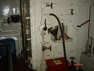
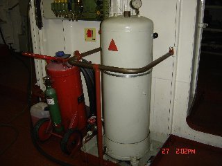
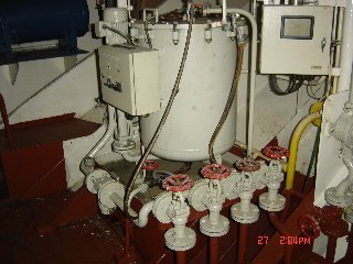
![]() FUEL OIL SYSTEM
FUEL OIL SYSTEM
1.
Technical description of the system (only Gas Oil
available on board)
1.1 Purpose of use
In accordance the fuel system ensures supply of fuel
for the following:
-operation of main engine SBA8
M 528
-operation of diesel plants No. 1 Deutz 6M 816oLLk
-operation of the harbour diesel No.2DEUTZ
KHD F5L413 FR
-operation of central heating burner
The system further allows:
-filling of the daily tank
-filling of the harbour diesel aggregate tank
-filling of fuel tanks No 1Ps, Stb and 2 Ps, Stb
-pumping out of leak tank 1060 Ltr
1.2 Main parts of the system
-1pc transfer fuel pump Q=1,39 m3/hour, 2,5/6 bar
-1 pc delivery fuel pump Q=1,39 m3/hour, 2,5/6 bar
-1 pc oil separator Q=1.380/1,100 l/hour
-1 pc CJC filter fuel filter
-1pc hand wing fuel pump K5, R 1 1/2"
-4 pcs fuel tank of total capacity V=111,6 m3
-1 pc daily fuel tank, capacity V=4,3 m3
-1 pc fuel waste tank 1060 l
|
|
|
1.3 Technical features
The fuel tanks with a capacity of 111,6 m3 of fuel
ensure continuous operation of the main engine, two units of diesel plants,
central heating boiler burner.
1.4 System description and its functions
1.4.1 Tanks
- system of re-pumping
The fuel stock is filled in four tanks. The fuel tanks are filled via a filling neck, which is located on the port side.
Daily fuel tank is situated on Ps of ER and can be filled by
the separator or electric transfer pump directly from fuel tanks. It is
possible to fill the tank with the manual pump. From day tank fuel can be
re-bunkering to each fuel tank by gravity. The daily plant fuel tank is
equipped with a overflow pipe, that ensures the outlet of excess fuel during
operation with fuel separator or electric transfer pump back to the fuel tank
No.2 Ps.
Harbour aggregate plant fuel tank is filled by the electric
transfer pump or by the separator. The tank has not
high level indicator or overflow of excess fuel to onother tank. Watchkeeping is
required during bunkering operation.
The waste fuel tank 1060Ltr is equipped with a device for
signalization, when the maximum level is reached. The tank is filled by sludge
flowing out from the daily fuel tank and diesel plant. The tank is further filled
from the main engine and from the collecting pans. Fuel further is transfered
by separator to daily tank.
1.4.2
Operation system for the main engine SBA8
M 528
Operation
of the main engine is ensured by supply of fuel from the daily tank across the
duplex filter into the engine. In case of main engine fuel oil pump failure the
spare pump type Allweiler type BAS 1650 can be turn on manually and delivery
fuel from the daily tank across the duplex filter into the engine.
1.4.3 System
for operation of diesel plants No 1.2 and 3
The
transfer fuel oil pump on the engine sucks fuel from the daily tank. Excess
fuel is transferred back to the daily tank.
1.4.4
Operation system for the harbour aggregate
The
transfer fuel pump on the engine sucks fuel from the harbour plant fuel tank
via duplex filter to the engine. Excess fuel is transferred back to the fuel
tank of the harbour plant.
1.4.5 System
for the central heating boiler burner
Transfer
pump of the burner sucks fuel from the daily tank via duplex filter into the
burner. Excess fuel is lead back to the daily tank.
|
|
1.4.6
Measuring and signalization
1.4.6.1
Remote measuring and signalization
-signalization of minimal level of fuel in the daily
tank
-signalization of maximal level of fuel in the leak
tank
-signalization of minimal level of fuel in the harbour
diesel plant tank
The transfer fuel pump is fed form the main
switchboard. Control and signalization is in a independent box located in the
engine room.
The spare fuel pump is fed from the main switchboard.
Its control and signalization is in an independent box in the engine room. Fuel
separator is fed form the main switchboard. In case of emergency, it is
possible to turn off the pump by an emergency switch in the main switchboard
room.
1.4.6.2
Local measuring
Under-pressure
and overpressure of the transfer pump is measured by mechanic vacuum meter and
manometer. Pressure behind the delivery pump is measured with mechanic
manometer.
1.4.7
General equipment of the system
Waste
fuel is collected in collector pans under emergency plant tank, under filters
and under the burner. It flows further by free flow to the leak fuel tank.
1.4.8
Overall arrangement
Fuel
system pipes are made form steel seamless tubes. The parts of the system are
connected with welded on flanges or with heavy screw connections. The pipe to
the engine is connected with flexible connections. The control fittings are
made form stainless steel in accordance with DIN prescription. Control fittings
are labeled according to their function. Pipes are painted with identification
color.
 LUBRICATION
OIL SYSTEM
LUBRICATION
OIL SYSTEM
1.
Technical description of the
system
1.1
Purpose
The oil system ensures:
-lubrication of the main engine
-lubrication of diesel aggregates No. 1,2 /they have
their own lubrication system with wet carter/
In further the system ensures:
-filling of the operation oil tank for the main engine
from the oil tank, by free flow or by hand pump
-re-pumping the oil from the main engine operation tank
with the help of the spare lubrication electric pump to the waste oil tank
-re-pumping the oil from the diesel plants with the
help of a hand pump via a flexible hose
-lubrication of the main engine with the spare gear
pump
-lubrication of the reverse gearbox carter with the
help of the spare electric pump
-separation and filtering of the main engine
lubrication oil during and beside operation
-filling of the shaft tube height tank from the shaft
tube
1.2 Main parts of the system
-1 pc Storage oil tank, V = 5,2 m3
-1 pc Sump oil tank for main engine, V = 1,6 m3
-1 pc Waste oil tank, V = 3,8 m3
-1 pc Spare lube-oil pump for
main engine, Q = 20 m3/h 6 bar
-1 pc Hand wing lub-oil pump K5, R 1 1/2"
-1 pc Spare lube-oil pump for
reverse gearbox, Q = 34 Ltr/min., 25bar
-Pipings with fittings,
measuring and signalling instruments
1.3
Technical characteristics
The
oil system with its oil supply (5,2 m3) ensures a continuous operation of the
main engine and two Diesel plants at nominal output.
1.4
Description of the system and its function
1.4.1 Storage oil tanks
-The storage oil tank can be filled via the deck
mounted necks, situated on the starboard side of a ship, on the main deck. It
is equipped with self-closing sludge valves. The tank for shaft tube is
equipped with level gauge.
-Under the main engine there is situated the daily oil
tank and the Diesel plants 1,2 have a wet carter.
-The daily tank of the main engine can be filled from
the storage oil tank by a gravity flow, the Diesel plants 1,2 can be filled
from a can. Pump out the main engine sump oil tank is possible with the help of
the spare lubrication pump to the waste oil tank.
The oil from auxiliery diesels crankcases can be
pumped out with the hinged manual pump via a flexible hose.
-The waste oil tank collects the oil from the
collecting pans situated under the fittings, pumps and separators.
Every tank is equipped with measuring bars, cleaning
manholes, deaerating pipes and floating device for signalization purposes:
-min
level of the oil in the main engine sump oil tank and in the shaft tube tank
-the
oil from the reverse gearbox carter is pumped out with the help of the spare
lubrication pump to the waste oil tank.
1.4.2
System for the main engine, SBV 8M 628, operation
The main engine has its own circulation lubrication.
The circulation pump, hinged on the engine, sucks the oil from the sump oil
tank, discharges it via the oil cooler and filters to the engine lubrication
points. The operation and emergency parameters in accordance with the Main
engine technical description.
1.4.2.1
Pre-lubrication of the main engine
The
main engine pre-lubrication before starting is done with the spare lubrication
pump. The oil is pressed via the back valves and therefore can be operated
independently from each other.
1.4.2.2
Main engine after cooling
After
a long lasting 100% fully load operation and after a sudden engine stop it is
possible to after cool the oil with the help of the spare lubrication pump and
with the spare cooling pump.
1.4.3 Oil system for the diesel plant
operation
The
diesel plants have their own circulation lubrication. The circulation pump,
hinged on the engine, sucks the oil from the crankcase and discharges via the
purifier, oil cooler to the engine. The operation and emergency parameters in
accordance with the diesel plant technical description.
1.4.3.1
Pre-lubrication of the diesel plants
The diesel plants are
pre-lubricated automatically during the beginning of their run, after starting.
1.4.5 Lubrication of the reverse gearbox
The
reverse gearbox is equipped with an independent circuit for lubrication and
control. There is connected to the network a spare lubrication and control pump
which can be used in the case when the hinged pump is damaged. The operation
and emergency parameters are in accordance with the reverse gearbox technical
description.
1. 4. 6 Description of the equipment's electric system
1.4.6.1
The main engine spare lubrication pump
Is
fed from the main switchboard. The control is carried out from the panel and manually
from the main switchboard as a pre-lubrication pump. At breakdowns of the main
engine's lubrication pump, during operation, there start to run automatically
the spare pump and at the same time there is signaled in safety system the
breakdown of the main lubrication pump.
1.4.6.2
The reverse gearbox spare lubrication pump
Is
fed from the main switchboard. The control is carried out from the panel and
manually from the main switchboard as a pre-lubrication pump. At breakdowns of
the reverse gearbox lubrication pump, during the main engine's operation, there
start to run automatically the spare pump and at the same time there is
signaled in safety system the breakdown of the main lubrication pump.
1.4.6.3
CJC oil filter
Is
on a common basement as a whole unit. It is fed from the main lub.oil system.
The signaling and control are in details described in the supplier' s
documentation.
|
|
1.4.7 General parts of the system
The waste oil is collected in
pans situated under fittings, pumps, from where it flows by a free flow to the
waste oil tank.
1.4.8 Overall design
The
oil system pipes are produced from steel, seamless tubes. The parts of the
piping are connected with welded on flanges or heavy screw connections. The
pipes are connected to the engines and to the electric pumps with the help of
flexible connections. The control fittings are made from cast steel, bronze or
eventually from malleable cast iron, the packings are in accordance with the
relevant DIN prescriptions and catalogs. The control fittings are marked with
identification labels which mark also their function. The pipings are marked
with differentiating colors.
2. Operation
manual
Individual functional circuits
of the oil system are connected and according to the required functions controlled
by fittings, in accordance with the functional scheme. Before starting the
equipment operation, check the oil level in the main engine daily oil tank, in
the crankcase of diesel plant, 1,2 and in the reverse gearbox carter.
 COOLING
WATER SYSTEM
COOLING
WATER SYSTEM
1. Technical description of the system
1.1 Purpose of use
The
cooling system, in accordance with functional scheme ensures:
-cooling of the main engine
-cooling of the diesel
aggregate
-cooling of the main engine's
oil
-cooling of the reverse gearbox
s oil
1.2 Main parts of the system
-circulating pump of the main
engine
-circulating pumps of the
diesel aggregate
-spare cooling pump (ballast
pump No.2)
-circulation pump for
preheating
-heat exchanger for preheating
-oil cooler for the reverse gearbox
-heat exchanger - heating
-water cooler for the main
engine
-water coolers for the diesel
aggregate
-equalization tank for the main
engine
-equalization tank for the
diesel plant
-pipings with fittings,
measuring and signalization instruments
1.3 Technical characteristics of the system
The cooling system is a one
circuit, indirect system. The cooling water circulates.
1.4 System and function description
1.4.1 Cooling of the main engine
The
main engine cooling is a one circuit system. The cooling pump sucks the water
via a thermo-regulator from the cooler and from the gearbox oil cooler and
discharges it across the engine, via thermo-controller back to the water
cooler. In the case when the cooling water temperature is low, the water does
not pass through the cooler but crosses a reduced circuit across the
thermo-regulator aside the cooler.
1.4.2 Cooling of the auxiliary
diesel-aggregates
Cooling
of the auxiliary diesel aggregate No.1 is a one circuit system. The cooling
system sucks the water from the cooler
and across the engine discharges it back to the cooler. Cooling of the
auxiliary diesel aggregate No.2 is provided by air. The fan of cooling system
sucks the air from the engine room space and across the engine discharges it
back to engine room.
1.4.3 Preheating of the engines
1.4.3.1 Preheating of the main engine
Preheating
of the main engine is carried out indirectly troughs the central heated heat
exchanger.
1.4.3.2 Preheating of the auxiliary diesel
aggregates
Preheating of the auxiliary
diesel plant No.1 is electric.
1.4.3.3
After cooling of the main engine
There is possible after long
lasting 100 % fully load operation and a sudden stop, to after the oil and the
whole system with the help of the spare cooling pump.
![]() 1.4.4 The
equalization tanks
1.4.4 The
equalization tanks
There
is arranged for main engine and auxiliery diesel No.1 an equalization tank
equipped with level gauge, cleaning holes, overflow pipe and outflow pipe. The
tanks are filled from the water-house system. The tanks are equipped with
floating switches to signal the minimum level of cooling water.
1.4.5 Measuring and signalization
1.4.5.1
Main engine
Pressure
measuring :
-before the main engine cooler
-behind the main engine cooler
-behind the spare cooling pump
Temperature
measurement:
-at the outlet from the main
engine
-at the reverse gearbox cooler
s inlet
-at the reverse gearbox cooler
s outlet
-before the main engine cooler
-behind the main engine cooler
Signalization of minimum level in the main engine's
equalization tank happens at 1/3 of the total volume.
1.4.5.2
Auxiliary diesel aggregates
Pressure
measurement
-before the DA1 cooler
-behind the DA1 coolers
Temperature
measurement
-before the DA1 cooler
-behind the DA1 cooler
Signaling
of minimum level in the auxiliary diesel aggregate equalization tanks happens
at 1/3 of the total volume.
1.4.6 Description of the system of the spare
cooling pump
For
emergancy reason when the hinged cooling water pump of main engine is broken
the ballast pump No.2 can be use as a spare. It is necessary to open and close
appropiate valves on the system accorging to the functional scheme. The pump is
fed from the main switchboard and it is controlled from the control box,
situated in the main engine room. There can be preselected a manual operation only.
During manual operation the pump works continuously.
1.4.7 Generally the design
The equalization tanks are made from steel plate. The
system is made from steel seamless tubes and it is protected with paint coat.
The system is painted with differentiating colors. The parts of the piping
system are connected with welded on flanges or screw connections. The lowest
places in the system are fitted with outflow fittings. All the fittings and
main parts are equipped with identification labels, describing their function
or use. Generally it is valid: The sucking pipe before the engine s pump and
spare cooling pump is connected with the equalization tank in order to flood
the system with water. The highest places of the system are connected with the
equalization tank to leas away the steam and air. The equalization tanks are
equipped with overpressure - under-pressure valve in order to equalize the
overpressure - under-pressure in the tank.
2. Operation manual
The
individual functional circuits of the cooling system are connected and
according to their function controlled by fittings in accordance with the
functional scheme. During operation follow the control instruments situated in
the equipment or near to the equipment.
The characteristics for cooling of the main engine,
DA1, DA2 are described in the operation and maintenance manuals supplied with
the equipment and which also form a part of the acceptance documentation.
![]() 3.
Maintenance manual
3.
Maintenance manual
Carry
out according to needs the cleaning of the water coolers in accordance with the
Maintenance manual for these equipment. Continuously check the tightness of
connections and fittings and when necessary, tighten or change the sealings. In
the case when it is necessary to drain the water from system, use the draining
fittings in the system s lowest places.
![]() BILGE AND BALLAST SYSTEM
BILGE AND BALLAST SYSTEM
|
|
|
1.
Technical description of the system
1.1 Purpose
The bilge system ensures pumping out the water from
individual watertight compartments of ship's body as well as cleaning of bilge
water from petroleum
1.2 Main parts
-1 pc Bilge-fire pump Allweiler type NTM 80-400, 60/120
m3/h, 4,2bar
-1 pc Ballast- Res.coolin water pump Allweiler type NTM
80-400, 60/120 m3/h, 4,2bar
-1 pc Cleaning equipment of bilge water type FRAM type
CPS 2,5 BV Mod.I 0,5m3/h,
-1 pc Hand wing pump K5, R 1 1/2"
-bildge water holding tank 4,4 m3
-waste oil tank 3,8 m3
1.3 Description of the system
1.3.1
Bilge-fire pump No. daA_01
Electrically driven bilge-fire pump, situated in
engine room, can pump out the water when needed from the following spaces:
-in regime it works as a bilge pump:
-via direct suction branch from underfloor space of
engine room,
-with the help of two suction baskets from underfloor
spaces of engine room,
-from bilge wells of cargo hold,
-from hydraulic ballast valves tunnel situated i engine
room
- in regime, if it works as a
fire pump, it sucks the water from connecting branch of sea chests.
Delivery of pump is led in regime „bilge pump"
over the ship's board. Delivery of pump is led in regime „fire pump" into
fire-fighting system.
1.3.2 Bilge
water purification (OWS) plant No. DaA 02
In
order to fulfil the requirements for purity of water, pumped out over the
ship's board, at engine room draining a ship is equipped with a purification
plant. Bilge water purification plant, situated in engine room, sucks oiled
water underfloor space in engine room, bildge water holding tank and separates
oil from water. Separated oil is delivered to waste oil tank and clean water is
delivered over the ship's board. The equipment is fitted with a valve on
delivering branch to enable checking of cleaned water.
|
|
1.3.3 Bildge
water holding tank and waste oil tank
Bilge
water holding tank is designed to collecting bilge water from the engine room
space by means of pump from OWS unit. Water from tank can be discharged by OWS
to overboard or by hand pump to the connection on the deck on the Ps side in
case of collecting to the outer facilities.
Waste oil tank can be emptied by means of reserve lub.oil pump main engine to the outer facilities by connection on the Ps side.
1.4
Design of the system
Pipeline is made from steel seamless pipes, connected
with flanges, zinc-galvanized, except for pipes led in fuel oil tanks which are
thick-wailed and black. Armatures, mounted directly onto ship's body shell, are
made from special shapeable cast iron and they have GL certificate. The others
are made from grey cast iron.
1.5
Control, measuring and signalization
Bilge-fire
pump is electrically fed from main switchboard. It is operated from a control
console. Bilge water purifier is fed from main switchboard. It is operated
locally. If petroleum substances in pumped out water exceed a value of 15 ppm,
the equipment will signal this exceeding in alarm-monitoring system and blocks
delivering of water over the ship's board. For checking purposes, all pumps are
equipped with measuring instruments, i.e. with manometers on delivery and
manovacuummeters on suction side.
In engine room and after part, in thrust unit room and
in collecting wells of cargo hold there is situated a signalization of water
presence. If water level reaches stated value, it is started an alarm via
alarm-monitoring system which calls the crew's attention to a need of drainage
of given spaces.
2.
Technical description of the ballast system
2.1 Purpose
The ballast system ensures:
-filling and discharging of ballast tanks,
-function of ship's trimming by suitable distribution
of ballast in tanks,
-emergency drainage of engine room.
2.2 Main
parts
-2 pcs Ballast pumps Allweiler type NTM 80-400, 60/120
m3/h, 4,2bar
-1 pc Bilge-stripping piston pump type S150 25m3/h, 4,0
bar
-17 pcs hydraulicaly controled of the ballast shutter's
DN 125
-distribution pipeline and armatures with suction
baskets, filters and checking Instruments.
![]()
2.3 Description of the system
2.3.1 Ballast
pumps
Both
electrically driven ballast pumps, situated in engine room, are on suction side
connected to connecting pipeline of sea chests. On delivery side they are
connected to main ballast distribution and to delivery over the ship's board.
To port side ballast pipeline, the following tanks are connected via manually
controlled flaps in the engine room and remote controlled flaps located in the
tunnel located in the engine room and cargo hold:
-Db Tk 1 Ps 133,4 m3
-Db Tk 2 Ps 116,8 m3
-Db Tk 3 Ps 140,2 m3
-Wt Tk 1 Ps 103,3 m3
-Wt Tk 2 Ps 116,8 m3
-Wt Tk 3 Ps 173,3 m3
-Wt Tk 4 Ps 140,6 m3
To starboard ballast pipeline, the following ballast
tanks are connected in the same way as on port side:
-Db Tk 1 Stb 133,4 m3
-Db Tk 2 Stb 116,8 m3
-Db Tk 3 Stb 140,2 m3
-Wt Tk 1 Stb103,3 m3
-Wt Tk 2 Stb 116,8 m3
-Wt Tk 3 Stb 173,3 m3
-Wt Tk 4 Stb 140,6 m3
-Forepeak 39,2 m3
-Afterpeak 34,8 m3
It is ensured a mutual changeability of ballast pumps
by suitable connection and delivery over both ship's sides. Ballast pumps also
ensure emergency drainage of engine room. For resting water from ballast tank
and drainage of engine room there is connected in the same way to the system
piston type pump. Ballast pumps are equipped with selfclosing automat as well
as with protection preventing the pumps running at dry condition.
2.4
Design of the system
Pipeline
is made from steel seamless tubes, connected with flanges, and is
zinc-galvanized, except for tubes led in fuel oil tanks which are thick-walled
and black. Armatures, mounted directly onto the ship's body shell, are made
from special shapeable cast iron with GL certificate, the others are made from
grey cast iron.
2.5 Control,
measuring, signalization
Ballast pumps are electrically fed from main
switchboard. Both pumps are operated from control console. In order to check,
the ballast pumps are equipped with measuring instruments, i. e. with
manometers on delivery and with manovacuummeters on suction side. Ballast
armatures are operated locally.
3.
Operation manuals
Individual
functional circuits of the bilge system are made according to the functional
scheme. Adjustment of armatures for single functions to be carried out
according to the functional scheme. For required individual functions it is
necessary to carry out all steps prescribed in accompanying documentation of
Supplier of individual equipment, to adjust and to put the equipment into
operation. Individual equipment must be manipulated according to own manuals
supplied together with the equipment by manufacturer.
4.
Maintenance manuals
Maintenance
of individual equipment to be carried out according to own manuals for
individual equipment that form a part of accompanying documentation of ship.
When needed, clean suction baskets and filters of pumps and ejectors.
Continuously, check tightness of connections of pipeline, armatures and
equipment.
In winter, exposed
parts of pipeline branches to be drained after using!