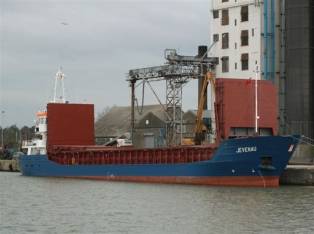
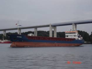
GENERAL PROVISIONS M/S PROVIDER
Main data MV Provider
status: In service
type: Mini Bulkcarriers (2001-3000 GT)
call sign: V2KF
imo no: 9356866
builders: Slovenske lodenice Komarno, a.s., Bratislava, SK
yard no: 2965
delivery: 2007-07-01
owner:
agent
port of registry: St. John's
flag: Antigua & Barbuda
class. hull: GL 100 A5 E G DG DBC
class. mach.: MC E AUT
Overall dimensions
tonnage GT [t]: 2461
tonnage NT [t]: 1369
deadweight [t]: 3700
lenght o.a. [m]: 87.84
lenght b.p. [m]: 81
breadth [m]: 12.8
depth to maindeck [m]: 7.1
depth to tweendeck [m]: 4.55
draught (summer) [m]: 5.51
|
|
|
, deck outfit
main Propulsion
engine: 1 MAK diesel, type 6 M 452 AK, 1070 kW at 425 rpm reduction 675 kW at
425 rpm; 1 reduction gear; 1 controllabe pitch propeller
auxiliary engines: 2 MAN Diesel D 2566
MTE 153 kW; 2 AEG DKBH 4256/04 generators 140 kVA, 380/220 V, 50 Hz, each;
1 shaft generator: AEG DKBH 4230/04 generator 94 kVA, 380/220 V, 50 Hz;
equipment: bow thruster 130 kW, 2 radars, gyro compass, autopilot, GPS, DGPS,
echo sounder, rate of turn indicator, SATCOM, VHF-unit, GMDSS fitted, electr.
hydr. steering gear hatch/hold 1 [m]: 56.55 x 10.20
Operating speed
- speed [kt]: 11.3
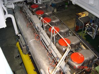
ENGINE
ACCOMODATION
Main Engine MaK 6M452 AK is situated on aft side the
vessel inside engine room:
|
|
|
-
Engine Control Room with Main switchboard:
|
|
|
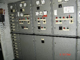
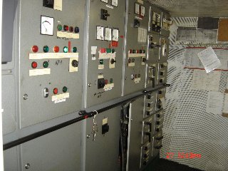
-
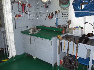
steering gear and workshop:
|
|
|
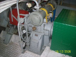
![]() MAIN ENGINE
MaK 6M452AK
MAIN ENGINE
MaK 6M452AK
1. Technical description
The propulsion plant serves for ship's propulsion.
The main parts are:
- The main engine, type MaK 6M
452AK Deutschland GmbH&Co KG - stand type, 6 cylinders, water-cooled,
non-reversal, with direct fuel injection, overcharged by cooled air, with
compressed air direct starter distributor and electric control. Engine type 6 M
452 AK, output 1070 kW, revolutions 425 /min, reduced to 675 kW at revolution
425/min.
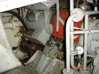
-The diesel engine is connected with reducing gearbox TACKE HUW-500 D by
elastic connector STROMAG GE. Line shafting with controllabe pitch propeller is
driven through a fast collar coupling on the propeller shaft of the gearbox.
The engine is equipped by a hydraulic regulator with revolution regulation and
stopping unit.
|
|
-Reducing gearbox TACKE HUW-500 D
gear ration i=1,7:1, with vertical offset of the engine and propeller shaft,
-Line shafting with controllabe pitch propeller diameter of 2500mm for
the ice class E.
Shaft
seals are made as follow: Blohm+Voss Compact Simplex fore 240,
aft 280 mm.
- Pneumatic remote engine revolutions control system enables control
from the panel of ME and in the wheelhouse.
2. Basic maintenance:
1 Check oil level - daily
2 Check cooling water level in
expansion tk - daily
3 Check engine exterior for loss of
oil, fuel and coolant - daily
4 Check operating pressures, temperatures and all others ME working
parameters, visual checks and running
noises - daily with engine running
5 Draining water from air receivers
- daily
6 Check level in leak oil tank and
empty it into day tank – daily, acc. need
7 Drain condense. water from
pneumatic control system - daily
8 Drain water before main starting
valve - before
starting
9 Checking the cooling water quality - weekly
10 Collecting sample of lub oil ME
system - monthly
11 Sending the lub oil sample for
analysis - monthly
12 Collecting sample of fuel (keep OB 1
year) - while
bunkering
13 Greasing reserve cooling water pump of
ME - monthly
14 Starting valve (servicing) - 5000h
15 Attached LO pump of ME check for
leakages, unusual noises and overheating - daily with engine running
16 Stand-by LO pump of ME check for
leakages, unusual noises and overheating - after start
17 Stand-by LO pump of ME bearing
regressing -
500 h
18 Stand-by fuel pump of ME check for
leakages, unusual noises and overheating - after start
19 Stand-by fuel pump of ME bearing
regressing - 500
h
20 Cleaning fuel oil duplex filter – daily
21 Cleaning LO separator - daily
22 LO
filter visual check of all filter cartridges
replace all static seals - yearly
23 Cleaning or changing the filter mat
of turbocharger - 100
h
24 Cleaning starting air filter of rotary filter - 1250 h
25 Check engine alarms, emergency stop devices - every 500 h
26 Checking injection nozzles - 1250 h
27 Checking valve clearance - 500 h
28 Governor oil change - 500 h
29 Starting valves (check) - 500 h
30 Camshaft bearings (removal and fitting) - 5000 h
31 T/C visual
inspection/check for abnormal noise - daily
32 T/C
compressor washing during operation (with clean water) - daily
33 T/C
cleaning/renewal of air filter mat at silencer - every 100 hrs
34 T/C check
fastening bolts at the feet, tighten all housing bolts and piping joints every - 1000 hrs
35 T/C oil change – every 500 hrs
2a. Basic
maintenance for CPP
1 Check oil level - daily - engine running
2 Greasing propeller head through main shaft - monthly - (engine stopped)
3 Greasing hydrounit - monthly - with
engine running
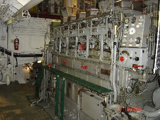
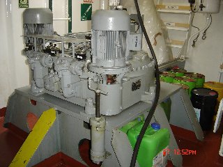
![]() THE DIESEL
PLANTS
THE DIESEL
PLANTS
1. Brief technical description
The
auxiliary diesel plants serve for the supply of electric energy to all
mechanisms and equipment which ensure the ship's normal operation.
Main parts:
-2 pcs of MAN Diesel D 2566 MTE 153 kW; 2 AEG DKBH 4256/04 generators 140
kVA
|
|
|
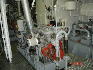
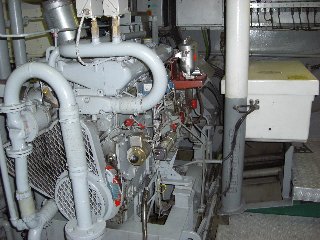
-1 pc of 1 shaft
generator: AEG DKBH 4230/04 generator 94 kVA, 380/220 V, 50 Hz
|
|
The
engines of the auxiliary diesel plants are overcharged, equipped with electric
starter, oil cooler, mechanic regulator of revolutions and with smooth electric
remote regulator of revolutions. The alternator is double-bearing, without
commutator brushes, with self-exciting and self-regulation, cooled by air, is
equipped with anti-condensate-heater. The shaft generator plant serves the
electric power supply during sea passage and can work in parallel mode with
diesel engines fro short time and only for switch over.
2. Basic maintenance
1 Check oil level - daily - engine
stopped
2 Check engine exterior for loss of
oil, fuel - daily
3 Check operating pressures, temperatures and all others
working parameters of the engine, visual checks and running noises - daily - with
engine running
4 Check fuel lines for leaks every
- 200 hrs
5 Check engine alarms, emergency stop devices - every 500 hrs
6 Cleaning of fuel pre-filter - every 250 hrs
7 Cleaning air filter - every 500 hrs
8 Change engine oil - every 250 hrs
9 Change oil filter cartridges - every 250 hrs
10 Inspecting/cleaning the Cooling System
- after first 2000 hrs
11 Check valve clearance, setting if necessary - every
1000 hrs
12 Check V-belt tension- every 250 hrs
13 Change of fuel filter - every 500 hrs
14 Check injectors, replacing if necessary - every 1000 hrs
2a. Basic
maintenance for shaft generator
1 Check oil level - daily - engine
stopped
2 Check operating working parameters of the shaft, visual
checks and running noises - daily - with engine running
3 Change oil- every 2000 h
4 Cleaning
oil filter upper- every 1000 h
5 Cleaning oil filter
lower- every
2000 h
6 Greasing bearings – not too much -
every 500 hrs
![]() FUEL OIL
SYSTEM
FUEL OIL
SYSTEM
1. Technical description of the system (only Gas
Oil available on board)
1.1 Purpose of use
The fuel system ensures supply of fuel for the
following:
-operation of main engine MaK 6M 452 AK
-operation of
diesel plants No. 1 and 2 MAN Diesel D 2566 MTE 153 kW
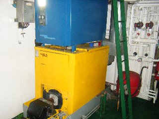
-operation of central heating burner
The system further allows:
-filling of the daily tank
-filling of the settling tank
-filling of the auxiliery diesel day tank Stb
-pumping out of leak tank
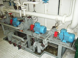
1.2 Main parts of the system
-2pc transfer fuel pump Q=10 m3/hour, 2,5 bar
-1 pc delivery fuel pump Q=2 m3/hour, 3 bar
-2 pc fuel oil pump ME(main and st-by) Q=1,5m3/h
-2 pc cooling nozzle ME pumps(main and st-by) Q=1m3/h
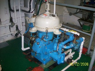
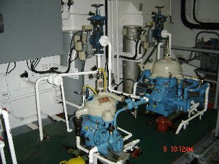
-1 pc oil separator Q=540 l/h
-pc 1 simple rough fuel filter 1pc duplex fuel filter
-1 pc duplex fuel fine filter
-3 pcs fuel tank of total capacity V=212 m3
-1 pc settling tank of total capacity V=8,3 m3
-1 pc daily fuel tank ME, capacity V=8,3 m3
-1 pc daily fuel tank auxiliery engines, capacity V=5,9 m3
-1 pc fuel tank for cooling ME nozzle 200 ltrs
-1 pc fuel leak tank 320 ltrs
|
|
|
1.3 Technical features
The fuel tanks with a capacity of 212 m3 of fuel ensure
continuous operation of the main engine, two units of diesel plants, central
heating boiler burner.
1.4 System description and its functions
1.4.1 Tanks
- system of re-pumping
The
fuel stock is filled in three tanks. The fuel tanks are filled via a filling
neck, which is located on the frame 23 starboard side and port side, the third
is located on the middle of the deck in front of superstructure.
Daily fuel tank for ME is filled by fuel separator..There are not
possibility to connect daily tk of M/E for ensure supply for auxiliaries
engines or burner. Outlet of excess fuel from the daily tank ensured by a
overflow pipe inside the tank to the fuel settling tank in 90% of high
of the tank sidewall.
The excess
fuel from the daily tank is led trough outlet and connection to the settling
tank PS and via
separated line and valve also to auxiliary day tk. Outlet of excess fuel from the
auxiliary day tk is ensured by a overflow pipe to the fuel tank No 3.
Daily fuel tank for auxilieries is filled by fuel separator or by fuel
transfer pump. Outlet of excess fuel from the daily auxiliary tank
ensured by a overflow pipe to the fuel tank No.3.The
tank can be switched into fuel main line for M/E
Settling fuel tank is filled with the transfer pump No.1 or
No.2. Tank could be filled with purified fuel
from the day tank via overflow connection in the sidewall. Outlet of excess
fuel from the daily& settling tank ensured
by a overflow pipe to the fuel tank No.2.The settling
fuel tank is equipped with a device for signalization when minimum level is
reached.
Fuel tank for cooling nozzles of ME is filled manually and equipped with a device for signalization, when
the maximum and minimum level is reached. The
separate cooler is connected to the cooling system of ME. Main and st-by
pumps provide cooling nozzle ME during operation.
The leak fuel tank 320Ltr is equipped with a device for signalization, when the maximum level is
reached. The tank is filled by sludge flowing out
from the daily fuel tank and settling tanks. The tank is further filled
from the main engine and from the collecting pans.
1.4.2
Operation system for the main engine MaK 6M452AK
Operation
of the main engine is ensured by supply of fuel from the daily tank or from
daily auxiliary tk across the duplex filter/water separator into the engine. In
case of main engine fuel oil pump failure the spare pump type PF 25 turns on
automatically and pumps fuel from the daily tank trough duplex filter through
to the engine. Excess fuel is transferred back to the daily tank.
1.4.3
System for operation of diesel plants No 1.2
The
transfer fuel oil pump on the engine sucks fuel from the auxiliary daily tank.
Excess fuel is transferred back to the auxiliary daily tank.
1.4.5
System for the central heating boiler burner
Transfer
pump of the burner sucks fuel from the auxiliary daily tank into the burner.
Excess fuel is lead back to the daily tank.
|
|
1.4.6 Measuring and signalization
1.4.6.1
Remote measuring and signalization
-signalization of minimal level of fuel in the daily tanks with signal
lamp
-signalization of minimal level of fuel in the settling tank with signal
lamp
-signalization of maximal level of fuel in the leak tank with signal lamp
-signalization of minimal level of fuel in the cooling nozzle ME tank
with signal lamp
-signalization of maximal level of fuel in the cooling nozzle ME tank
with signal lamp
The transfer fuel pump is fed form the main
switchboard. Control is in an independent box located in the engine room.
The spare fuel pump is fed from the main switchboard.
Its control is in an independent box in the engine room.
Fuel separator is fed form the main switchboard. Its control is in an independent box in the engine room
1.4.6.2 Local
measuring
Under-pressure
and overpressure of the transfer pump is measured by mechanic vacuum meter and
manometer. Pressure behind the delivery pump is measured with mechanic
manometer.
1.4.7 General
equipment of the system
Waste
fuel is collected in collector connected to plant tank, under filters and under
the burner. It flows further by free flow to the waste fuel tank.
1.4.8 Overall
arrangement
Fuel
system pipes are made form steel seamless tubes. The parts of the system are
connected with welded on flanges or with heavy screw connections. The control
fittings are made form stainless steel in accordance with DIN prescription.
Control fittings are labeled according to their function. Pipes are painted
with identification color.
![]() LUBRICATION
OIL SYSTEM
LUBRICATION
OIL SYSTEM
1. Technical
description of the system
1.1 Purpose
The oil system in accordance ensures:
-lubrication of the main engine
-lubrication of diesel aggregates No. 1,2 /they have their own
lubrication system with wet carter/
In further the system ensures:
-filling of the operation oil tank for the main engine from the spare oil tank, with the
help of reserve lubrication oil pump or by M/E circulation pump
-emptying of circulation oil tk of M/E via valve to the
old oil tk.
-pumping out the oil from the main
engine operation tank with the help of the spare lubrication electric pump on
the deck Marpol connection
-re-pumping the oil from the diesel plants with the help of a hand pump
and transfer into the waste oil tank
-lubrication of the main engine with the spare gear pump
-separation of the main engine lubrication oil during and beside
operation
-filling of the shaft tube height tank from the shaft tube and reverse
gearbox oil tank
1.2 Main parts of the system
-1 pc Storage oil tank, V = 6,7 m3
-1 pc Circulating oil tank for main engine, V = 1,1 m3
-1 pc Old oil tank, V = 2,2 m3
-1 pc Sludge tank from separators, V = 2,2 m3
-2 pc (main and spare) lube-oil pump for main engine, Q = 1,2 m3
/h, 8bar
-1 pc Spare lube-oil pump for reverse gearbox, Q = 0,4 m3 /h,
5bar
-Pipings with fittings, measuring and signalling instruments
-1 pc Oil separator Ef.Q
= 420 1/h
|
|
1.3 Technical characteristics
The
oil system with its oil supply (5,7 m3) ensures a continuous operation of the
main engine and three Diesel plants.
1.4 Description of the system and its function
1.4.1 Storage oil tanks
-The storage oil tanks can be filled via the deck mounted necks, situated
on the port side of a ship, on aft part. The storage oil tank is equipped with
level gauge.
-On the Ps of the main engine there is situated the circulating oil tank.
Diesel plants 1,2 have a wet carster.
-The circulating tank of the main engine can be filled from the storage
oil tank by a st-by lub.oil pump or with the help of
M/E circulation pump, the Diesel plants 1,2 can be filled from a can.
Pump out the main engine circulating oil tank is possible with the help of the
spare lubrication pump on the deck. There is
also valve connected to old oil tank to ensure gravity emptied of circulating
tank.
The oil from the DA 1-2
crankcases can be pumped out with the hinged manual pump via a flexible hose.
Every tank is equipped with measuring bars, cleaning manholes, deaerating pipes and floating device for
signalization purposes:
-min level of the oil in the main engine oil tank and in the shaft tube
tank
-max oil level in the old oil tank and in the sludge
tank.
1.4.2 System for the main engine, MaK 6M 452 AK operation
The main engine has its own circulation lubrication.
The circulation pump, hinged on the engine, sucks the oil from the circulating
oil tank, discharges it via the oil cooler and filters to the engine
lubrication points. In case of failure the hinged pump, two st-by pumps switch
on automatically – one pump is transfering oil
from ME to circulating tank, the other one from tank to ME. The operation and emergency
parameters in accordance with the Main engine technical descripstion.
1.4.2.1 Pre-lubrication of the main engine
The
main engine pre-lubrication before starting is done with the spare lubrication
pumps. The oil is pressed via the back valves and therefore can be operated
independently from each other.
1.4.2.2 Main engine after cooling
After
a long lasting 100% fully load operation and after a sudden engine stop it is
possible to after cool the oil with the help of the spare lubrication pump and
with the spare cooling pump.
1.4.3 Oil system for the
diesel plants operation
The
diesel plants have their own circulation lubricastion. The circulation pump,
hinged on the engine, sucks the oil from the crankcase and discharges via the
purifier, oil cooler to the engine. The operation and emergency parameters in
accordance with the diesel plant s technical
description.
1.4.3.1 Pre-lubrication of the diesel plants
The diesel plants
are pre-lubricated automatically during the beginning of their run, after
starting.
1.4.5 Lubrication of the
reverse gearbox
The
reverse gearbox is equipped with an independent circuit for lubrication and
control. There is connected to the network a spare lubrication and control pump
which can be used in the case when the hinged pump is damaged. The operation
and emergency parameters are in accordance with the reverse gearbox technical
description.
1. 4. 6 Description of the equipment's electric system
1.4.6.1 The main engine spare lubrication pump
Is
fed from the main switchboard. The control is carried out from the panel and
manually switched on as a pre-lubrication pump. At breakdowns of the main
engine's lubrication pump, during operation, the safety system start to run
automatically the spare pump and at the same time there is signaled in safety
system the breakdown of the main lubrication pump.
1.4.6.2 The reverse gearbox spare lubrication pump
Is
fed from the main switchboard. The control is carried out from the panel and
manually switched on as a pre-lubrication pump. At breakdowns of the reverse
gearbox lubrication pump, during the main engine's operation, there start to
run automatically the spare pump and at the same time there is signaled in
safety system the breakdown of the main lubrication pump.
1.4.6.3 The oil separator
Is
on a common basement with the automatics as a whole unit with the fuel oil
separator. It is fed from the main switchboard. The automatics itself, as well
as the signaling and control are in details described in the supplier' s
documentation.
1.4.7 General parts of the
system
The waste oil is
collected in pans situated under fittings, pumps, from where it flows by a free
flow to the waste oil tank.
1.4.8 Overall design
The
oil system pipes are produced from steel, seamless tubes. The parts of the
piping are connected with welded on flanges or heavy screw connections. The
pipes are connected to the engines and to the electric pumps with the help of
flexible connections. The control fittings are made from cast steel, bronze or
eventually from malleable cast iron, the packings are in accordance with the
relevant DIN prescriptions and catalogs. The control fittings are marked with
identification labels which mark also their function. The pipings are marked with
differentiating colors.
2. Operation
manual
Individual functional circuits of
the oil system are connected and according to the required functions controlled
by fittings, in accordance with the functional scheme. Before starting the
equipment s operation, check the oil level in the main engine circulation oil tank, in the crankcase of diesel
plant, 1,2 in the hydraulic CPP unit tank of
propeller and in the reverse gearbox carter.
![]() COOLING
WATER SYSTEM
COOLING
WATER SYSTEM
1. Technical description of
the system
1.1 Purpose of use
The cooling system ensures:
-cooling of the main engine
-cooling of the main engine's oil
-cooling of the reverse gearbox s oil
-cooling of the hydraulic unit oil of the propeller
-cooling of the circulation fuel of cooling injection
valves
1.2 Main parts of the system
-circulating pump of the main engine
-spare cooling pump
-circulation pump for preheating
-heat exchanger for preheating
-oil cooler for the reverse gearbox
-oil cooler of hydraulic unit of propeller
-cooler of circulation fuel system for cooling injection
valves
-oil sensor
-heat exchanger - heating
-water cooler for the main engine
-equalization tank for the main engine and diesel plants
-pipings with fittings, measuring and signalization instruments
1.3 Technical characteristics
of the system
The cooling system
is a one circuit, indirect system. The cooling water circulates.
1.4 System and function
description
1.4.1 Cooling of the main
engine
The
main engine cooling is a one circuit system. The cooling pump sucks the water
via a thermo-regulator from the cooler and from the gearbox oil cooler and
discharges it across the engine, via thermo-controller back to the water
cooler. In the case when the cooling water temperature is low, the water does
not pass through the cooler but crosses a reduced circuit across the
thermo-regulator aside the cooler.
1.4.2 Cooling of the
auxiliary diesel-aggregates
Cooling
of the auxiliary diesel aggregates is is a one circuit system. The cooling pump
sucks the water via a thermo-regulator from the cooler and from the gearbox oil
cooler and discharges it across the engine, via thermo-controller back to the
water cooler. In the case when the cooling water temperature is low, the water
does not pass through the cooler but crosses a reduced circuit across the
thermo-regulator aside the cooler.
1.4.3 Preheating of the
engines
1.4.3.1 Preheating of the main
engine
Preheating
of the main engine is carried out indirectly troughs the central heated heat
exchanger.
1.4.3.3 After cooling of the main engine
There is possible
after long lasting 100 % fully load operation and a sudden stop, to after the
oil and the whole system with the help of the spare cooling pump.
![]() 1.4.4 The equalization tanks
1.4.4 The equalization tanks
There
is arranged for main engine an equalization tank equipped with level gauge,
cleaning holes, overflow pipe and outflow pipe. The tanks are filled from the
water-house system. The tanks are equipped with floating switches to signal the
minimum level of cooling water.
1.4.5 Measuring and
signalization
1.4.5.1 Main engine
Pressure measuring :
-before the main engine cooler
-behind the main engine cooler
-behind the spare cooling pump
Temperature measurement:
-at the outlet from the main engine
-at the reverse gearbox cooler inlet
-at the reverse gearbox cooler outlet
-before the main engine cooler
-behind the main engine cooler
Signalization of minimum level in the main engine's
equalization tank happens at 1/3 of the total volume.
1.4.6 Description of the
system's electric parts-of the spare cooling pump
It
is fed from the main switchboard and it is controlled from the control box,
situated in the main engine room. There can be preselected a manual operation
only. During manual operation the pump works continuously.
1.4.7 Generally the design
The equalization tank is made from steel plate. The
system is made from steel seamless tubes and it is protected with paint coat.
The system is painted with differentiating colors. The parts of the piping
system are connected with welded on flanges or screw connections. The lowest
places in the system are fitted with outflow fittings. All the fittings and
main parts are equipped with identification labels, describing their function
or use. Generally it is valid: The sucking pipe before the engine pump and
spare cooling pump is connected with the equalization tank in order to flood
the system with water. The highest places of the system are connected with the
equalization tank to leas away the steam and air.
2. Operation manual
The
individual functional circuits of the cooling system are connected and
according to their function controlled by fittings in accordance with the
functional scheme. During operation follow the control instruments situated in
the equipment or near to the equipment.
The characteristics for cooling of the main engine is
described in the Operation and maintenance manuals supplied with the equipment
and which also form a part of the acceptance documentation.
![]() 3. Maintenance manual
3. Maintenance manual
Carry
out according to needs the cleaning of the water coolers in accordance with the
Maintenance manual for these equipment. Continuously check the tightness of
connections and fittings and when necessary, tighten or change the sealings. In
the case when it is necessary to drain the water from system, use the draining
fittings in the system lowest places.
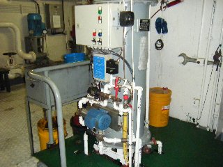
![]() BILGE AND
BALLAST SYSTEM
BILGE AND
BALLAST SYSTEM
- Technical description of the system
1.1 Purpose
The bilge system ensures pumping out the water from
individual watertight compartments of ship's body as well as cleaning of bilge
water from petroleum.
1.2 Main parts,
-1 pc Bildge-fire pump SFS 60 30m3/h
-1 pc Cleaning equipment of bilge water type Alandia MARI-SEP 0,75 m3/h,
-1 pc Pump for outpouring of used oil and sludge type VK 0211WW, 2,7 m3/h
1.3 Description of the system
1.3.1
Bilge-fire pump
Electrically driven bilge pump, situated in engine
room, can pump out the water when needed from the following spaces:
-in regime it works as a bilge pump:
-via direct suction branch from underfloor space of engine room,
-with the help of three suction baskets from underfloor spaces of engine
room,
-from two bilge wells of cargo hold,
- in regime, if it works as a fire pump, it sucks the
water from connecting branch of sea chests.
Delivery of pump is led in regime „bilge pump" over
the ship's board. Delivery of pump is led in regime „fire pump" into
fire-fighting system.
1.3.2 Bilge
water purification (OWS) plant No. daA
In
order to fulfil the requirements for purity of water, pumped out over the
ship's board, at engine room draining a ship is equipped with a purification
plant.Bilge water purification plant, situated in engine room, sucks oiled
water underfloor space in engine room and separates oil from water. Separated
oil is delivered to waste oil tank and clean water is delivered over the ship's
board. The equipment is fitted with a valve on delivering branch to enable
checking of cleaned water.
|
|
1.3.3 For fore
spaces removing of bilges there are exist separated
bilge system connected to emergency fire pump
The emergency fire pump sucks the water, when needed, from the following spaces:
-from thrust unit room
-.from cargo hold forward part-STBD&PS
-from sump of space of bowthruster electric motor
Delivery of pump is over the ship's board via
reverse-closing valve.
1.4 Design of
the system
Pipeline is made from steel seamless pipes, connected
with flanges, zinc-galvanized, except for pipes led in fuel oil tanks which are
thick-wailed and black. Armatures, mounted directly onto ship's body shell, are
made from special shapeable cast iron and they have GL certificate. The others
are made from grey cast iron.
1.5 Control,
measuring and signalization
Bilge-fire
pump electrically fed from main switchboard. It is operated from a control
console. Bilge water purifier main switchboard. It is operated locally. If
petroleum substances in pumped out water exceed a value of 15 ppm, the
equipment will signal this exceeding in alarm-monitoring system and blocks
delivering of water over the ship's board. For checking purposes, all pumps are
equipped with measuring instruments, i.e. with manometers on delivery and
manovacuummeters on suction side.
In engine room and after part, in thrust unit room and
in collecting wells of cargo hold there is situated a signalization of water presence.
If water level reaches stated value, it is started an alarm via
alarm-monitoring system which calls the crew's attention to a need of drainage
of given spaces.
Main fire pump located in the E/R STBD on the wall of cargo
hold have possibility via marked emergency suction valve - discharging of
bilges fm machinery spaces directly outboard in emergency cases.
2. Technical
description of the ballast system
2.1 Purpose
The ballast system ensures:
-filling and discharging of ballast tanks,
-function of ship's trimming by suitable distribution of ballast in
tanks,
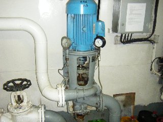
2.2 Main
parts
- 2 pc ballast
Ps, Stb pump SFS 120A 175m3/h 3,0 bar
- 1 pc Emergancy fire pump 63 SWL 55M509 63m3/h 3,0 bar
-13 pcs hydraulicaly controled of the ballast shutter's DN 150
-distribution pipeline and armatures with suction baskets, filters and
checking Instruments.
|
|
![]()
2.3 Description of the system
2.3.1 Ballast
pumps
Both
electrically driven ballast pumps, situated in engine room, are on suction side
connected to connecting pipeline of sea chests. On delivery side they are
connected to main ballast distribution and to delivery over the ship's board.
To port side ballast pipeline, the following tanks are connected via manually
controlled flaps in the engine room ballast system and remote controlled flaps
located in the engine room bildge space under the floor:
-DB Tk 1 Ps
-DB Tk 2 Ps
-DB Tk 3 Ps
-DB Tk 4 Ps
-DB Tk 5 Ps
-STk 1 Ps
-STk 2 Ps
-Afterpeak Ps and Stb
To starboard ballast pipeline, the following ballast
tanks are connected in the same way as on port side:
-DB Tk 1 Stb
-DB Tk 2 Stb
-DB Tk 3 Stb
-DB Tk 4 Stb
-DB Tk 5 Stb
-STk 1 Stb
-STk 2 Stb
-Afterpeak Ps and Stb
-Forepeak can be filled only by emergancy fire pump on the bow.Emergency fire pump in bowthruster accommodation is connected
also to the bow bilge system
It is ensured a mutual changeability of ballast pumps
by suitable connection and delivery over both ship's sides. Ballast pumps do
not ensure emergency drainage of engine room. Ballast pump can not running at dry condition.
2.3.2 Ballast
drying No. dbA_02
Drying
of single ballast tanks is carried out with the help of ballst pumps situated
in engine room. Its function is secured by appropriate adjustment of armatures.
2.4 Design
of the system
Pipeline
is made from steel seamless tubes, connected with flanges, and is
zinc-galvanized, except for tubes led in fuel oil tanks which are thick-walled
and black. Armatures, mounted directly onto the ship's body shell, are made
from special shapeable cast iron with GL certificate, the others are made from
grey cast iron.
2.5 Control,
measuring, signalization
Ballast pumps are electrically fed from main
switchboard. Both pumps are operated from control console. In order to check,
the ballast tanks are equipped with measuring instruments, i. e. with
manometers on delivery and with manovacuummeters on suction side. Ballast
armatures are operated locally.
3. Operation
manuals
Individual
functional circuits of the bilge system are made according to the functional scheme.
Adjustment of armatures for single functions to be carried out according to the
Functional scheme. For required individual functions it is necessary to carry
out all steps prescribed in accompanying documentation of Supplier of
individual equipment, to adjust and to put the equipment into operation.
Individual equipment must be manipulated according to own manuals supplied
together with the equipment by manufacturer.
4.
Maintenance manuals
Maintenance
of individual equipment to be carried out according to own manuals for
individual equipment that form a part of accompanying documentation of ship.
When needed, clean suction baskets and filters of pumps and ejectors.
Continuously, check tightness of connections of pipeline, armatures and equipment.
In winter, exposed parts
of pipeline branches to be drained after using!